Verilator Pt.2: Basics of SystemVerilog verification using C++

In Part 1, we discussed the basics of using Verilator and writing C++ testbenches for Verilog/SystemVerilog modules. In this guide, we will improve the testbench with randomized initial values for signals, add a reset signal, and lastly add input stimulus and output checking to get going with some basic verification functionality.
Getting started ⌗
This guide is a direct continuation from Part 1. You can get the finished sources for the example Verilator project used in this tutorial from Github and explore as you wish:
    git clone https://github.com/n-kremeris/verilator_basics
    git checkout verilator_pt2
Or, follow the guide below as we continue from Part 1.
Long commands are for troglodytes ⌗
Before doing anything to our testbench, it must be said that nobody likes typing the same commands over and over again. And as we’re not cavemen, we will use (Make)[https://www.gnu.org/software/make/] to quickly build and run our simulation, swiftly advancing our hardware design capabilities into the stone age.
Most of the build commands used in the Makefile below should be familiar from Part 1, but lets briefly go over them again just in case:
verilator -Wall --trace -cc alu.sv --exe tb_alu.cpp ⌗
This converts our alu.sv source to C++ and generates build files for building the simulation executable. We use -Wall to enable all C++ errors, --trace to enable waveform tracing, -cc alu.sv to convert our alu.sv module to C++, and --exe tb_alu.cpp to tell Verilator which file is our C++ testbench.
make -C obj_dir -f Valu.mk Valu ⌗
This builds our simulation executable from the testbench and the converted sources. We tell Make to change the working directory to obj_dir, use the build file named Valu.mk and build the target named Valu
./obj_dir/Valu ⌗
This runs our simulation executable which simulates the testbench and generates our waveforms.
In your work directory, create a file named Makefile and paste the following contents:
NOTE: Do not drag-select and CTRL+C, instead, hover your mouse and click on the newly appeared COPY button on the top right corner of the text box.
MODULE=alu

.PHONY:sim
sim: waveform.vcd

.PHONY:verilate
verilate: .stamp.verilate

.PHONY:build
build: obj_dir/Valu

.PHONY:waves
waves: waveform.vcd
	@echo
	@echo "### WAVES ###"
	gtkwave waveform.vcd

waveform.vcd: ./obj_dir/V$(MODULE)
	@echo
	@echo "### SIMULATING ###"
	@./obj_dir/V$(MODULE)

./obj_dir/V$(MODULE): .stamp.verilate
	@echo
	@echo "### BUILDING SIM ###"
	make -C obj_dir -f V$(MODULE).mk V$(MODULE)

.stamp.verilate: $(MODULE).sv tb_$(MODULE).cpp
	@echo
	@echo "### VERILATING ###"
	verilator -Wall --trace -cc $(MODULE).sv --exe tb_$(MODULE).cpp
	@touch .stamp.verilate

.PHONY:lint
lint: $(MODULE).sv
	verilator --lint-only $(MODULE).sv

.PHONY: clean
clean:
	rm -rf .stamp.*;
	rm -rf ./obj_dir
	rm -rf waveform.vcd
The Makefile should be straightforward for those who are familiar with Make. If you have not used Make before, please take a look another one of my guides on using Make for simulation.
Once you have saved the file, you will be able to quickly rebuild the entire simulation by running make sim in your terminal, open GTKWave using make waves, Verilate your design using make verilate, or build the verilated sources using make build.
Note that there is an aditional make lint target, which calls Verilator with --lint-only. This is useful to quickly parse your Verilog/SystemVerilog source files and check for problems. This can be used to check over your sources even if you’re not using Verilator for simulating.
Lastly there’s a make clean target that removes all of the junk generated in the build progress.
And with all of that out of the way, let’s make that testbench sparkle.
Randomized initial values ⌗
One of the observations from Part 1 was that Verilator is a two state simulator, meaning that it only supports logic values of 1 and 0, and there is no support for X (and only limited support for Z). Verilator therefore initializes all signals to 0 by default, which can be seen in Fig.1 from our previous simulation results:
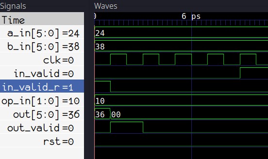 Fig. 1: Everything is initialized to 0 by default
Additionally, if you have code that assigns X to a wire or reg, then that by default also gets the value of 0.
We can, however, change this behavior via command-line parameters - we can have Verilator initialize all signals to 1, or, better yet, to a random value. This will allow us to check if our reset signal works, once we add it to the testbench.
To make our testbench initialize signals to random values, we first need to call Verilated::commandArgs(argc, argv); before creating the DUT object:
int main(int argc, char** argv, char** env) {
    Verilated::commandArgs(argc, argv);
    Valu *dut = new Valu;
<...>
Then, we need to update our verilation target build command by adding --x-assign unique--x-initial unique
verilator -Wall --trace --x-assign unique --x-initial unique -cc $(MODULE).sv --exe tb_$(MODULE).cpp
Lastly, we need to pass +verilator+rand+reset+2 to our simulation executable, to set set the runtime signal initialization technique to random. This means changing the Line 21 in our Makefile to:
@./obj_dir/V$(MODULE) +verilator+rand+reset+2
Now if we do make clean and make waves, we will see that signals are now initialized to random values at the start of the simulation:
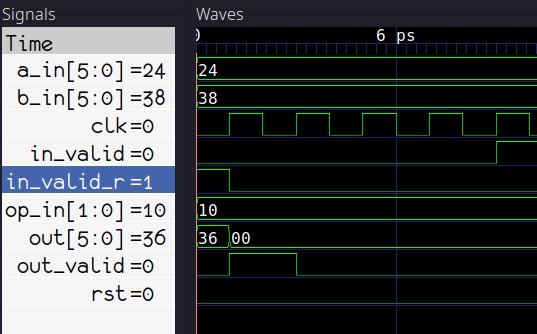 Fig. 2: Random initialization
With the signals now randomised, we can take a look at applying our reset signal.
DUT reset ⌗
To reset our DUT and it’s input signals, we update the main loop of our testbench to look like this:
while (sim_time < MAX_SIM_TIME) {
    dut->rst = 0;
    if(sim_time > 1 && sim_time < 5){
        dut->rst = 1;
        dut->a_in = 0;
        dut->b_in = 0;
        dut->op_in = 0;
        dut->in_valid = 0;
    }

    dut->clk ^= 1;
    dut->eval();
    m_trace->dump(sim_time);
    sim_time++;
}
On Line 3, I have arbitrarily picked that I want my reset to happen between clock edges 3 and 5. You may of course adjust this if required.
On Line 4, the reset is asserted high, and on the succeding lines all the inputs to the DUT are reset to 0.
Lines 11-14 are not modified. We tick the clock and increment the time counter.
Line 2 is added to reset the counter back to 0 on subsequent loop iterations. Together, lines 2-3-4 would be equivalent to the following in SystemVerilog code:
always_comb begin
    dut.rst = 1'b0;
    if (sim_time >= 3 && sim_time < 6) begin
        dut.rst = 1'b1;
    end
end
Re-running the simulation now gives us this:
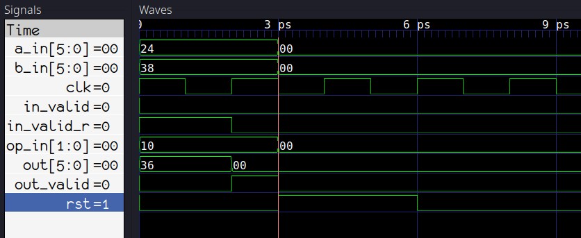 Fig. 3: Reset signal in action
As you can see from Figure 3, our reset signal is successfully generated in the testbench. To keep the main loop a bit cleaner, lets move the reset stuff into a separate function outside the main():
void dut_reset (Valu *dut, vluint64_t &sim_time){
    dut->rst = 0;
    if(sim_time >= 3 && sim_time < 6){
        dut->rst = 1;
        dut->a_in = 0;
        dut->b_in = 0;
        dut->op_in = 0;
        dut->in_valid = 0;
    }
}
Then we add a call to dut_reset to the main loop:
while (sim_time < MAX_SIM_TIME) {
    dut_reset(dut, sim_time);

    dut->clk ^= 1;
    dut->eval();
    m_trace->dump(sim_time);
    sim_time++;
}
Now that our reset works, lets take a look at some actual stimuli and verification code.
Basic Verification ⌗
At this point, we have the following in our main simulation loop:
while (sim_time < MAX_SIM_TIME) {
    dut_reset(dut, sim_time);

    dut->clk ^= 1;
    dut->eval();
    m_trace->dump(sim_time);
    sim_time++;
}
Now if we were simulating a Verilog/SystemVerilog testbench as the dut instead of our alu module, we could add a check for Verilated::gotFinish() and stop the simulation if that is set to true. This happens when $finish() gets called from Verilog/SystemVerilog. Our C++ testbench would then be sufficient for simulating a Verilog/SystemVerilog testbench.
That’s not going to be enough for us though, as we need to insert stimulus and verification code somewhere in the C++ testbench main loop to drive and check our DUT.
Clock edge counter ⌗
There are many ways to skin a dead horse with a single stone, but here is what we’re going to do for now:
Firstly, we’ll create a new variable for counting positive clock edges. This variable will be of the same type as sim_time:
    vluint64_t sim_time = 0;
    vluint64_t posedge_cnt = 0;
Next, we modify our edge generation code by adding a positive edge counter:
dut->clk ^= 1;            // Invert clock
dut->eval();              // Evaluate dut on the current edge
if(dut->clk == 1){
    posedge_cnt++;        // Increment posedge counter if clk is 1
}
m_trace->dump(sim_time);  // Dump to waveform.vcd
sim_time++;               // Advance simulation time
Adding that counter between eval and dump gives us something similar to the following in Verilog:
initial posedge_cnt <= '0;
always_ff @ (posedge clk, posedge rst) begin
    posedge_cnt <= posedge_cnt + 1'b1;
end
And at this point, we can finally start verifying our ALU.
Primitive DUT stimuli and checks ⌗
Let’s take a look again at the expected waveforms for our ALU:
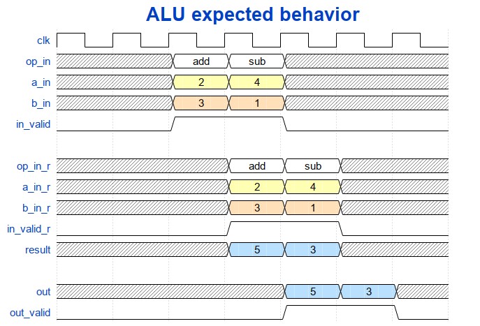 Fig. 4: Expected ALU behavior
Ignoring the a,b and operation inputs, as well as the data output, lets first check that our input valid signal propagates to the output.
We know that we have 2 register stages, which, when simplified, would look like this:
always_ff @ (posedge clk) begin
    in_valid_r <= in_valid;
    out_valid <= out_valid_r;
end
So if we applied 1 to in_valid on the 5th positive clock edge, we should see a 1 on out_valid after two clock cycles, or in other words, on the 7th positive clock edge. Here’s how we check for that:
while (sim_time < MAX_SIM_TIME) {
    dut_reset(dut, sim_time);

    dut->clk ^= 1;
    dut->eval();

    dut->in_valid = 0;
    if (dut->clk == 1){
        posedge_cnt++;
        if (posedge_cnt == 5){
            dut->in_valid = 1;       // assert in_valid on 5th cc
        }
        if (posedge_cnt == 7){
            if (dut->out_valid != 1) // check in_valid on 7th cc
                std::cout << "ERROR!" << std::endl;
        }
    }

    m_trace->dump(sim_time);
    sim_time++;
}
What the highlighted code accomplishes would be similar to this:
always_comb begin
    in_valid = 0;
    if (posedge_cnt == 5)
        in_valid = 1;

    if (posedge_cnt == 7)
        assert (out_valid == 1) else $error("ERROR!")
end
And here is how it all works when simulated:
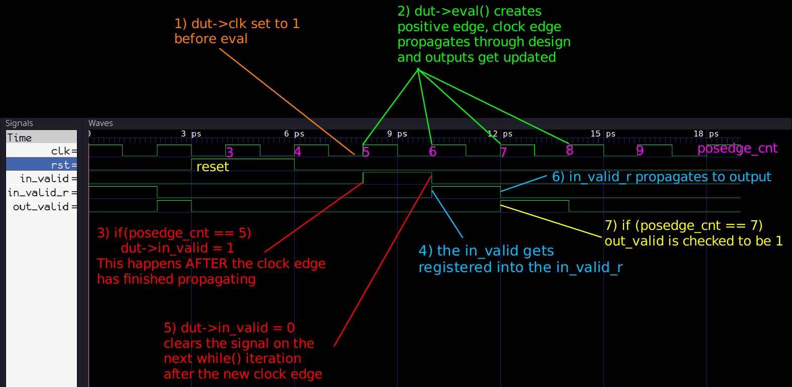 Fig. 5: Graphic explanation for the valid checking
(click here for high res version)
The main point here is to make sure that stimuli/checking code you write follows this order of operations:
-
Set clock to 1, evaluate to create positive edge, and then set inputs / check outputs before dumping and incrementing sim time.
-
On the next positive clock edge inside the
while()loop, the inputs set previously will propagate into the design duringeval, and then right after eval the inputs should be reset to their default values.
Assertion-like signal monitoring ⌗
Setting the in_valid on the 5th edge and checking that the out_valid is 1 definitely works, but if we wanted to check the valids on more clock cycles, we would need to add a lot more checks. Additionally, we’re not checking that out_valid is 0 where it’s supposed to be, meaning our out_valid could be stuck at 1 and the testbench would not fail. Our verification code could therefore be significantly improved by writing some C++ code to continuously monitor in_valid and out_valid, similarly to how SystemVerilog assertions work.
We can write a function for this as follows:
#define VERIF_START_TIME 7
void check_out_valid(Valu *dut, vluint64_t &sim_time){
    static unsigned char in_valid = 0; //in valid from current cycle
    static unsigned char in_valid_d = 0; //delayed in_valid
    static unsigned char out_valid_exp = 0; //expected out_valid value

    if (sim_time >= VERIF_START_TIME) {
        // note the order!
        out_valid_exp = in_valid_d;
        in_valid_d = in_valid;
        in_valid = dut->in_valid;
        if (out_valid_exp != dut->out_valid) {
            std::cout << "ERROR: out_valid mismatch, "
                << "exp: " << (int)(out_valid_exp)
                << " recv: " << (int)(dut->out_valid)
                << " simtime: " << sim_time << std::endl;
        }
    }
}
The VERIF_START_TIME is needed to make sure we are not running this checking code before or during reset, to prevent false error detection. If you refer to Fig. 5, you will see that rst goes back to 0 on 6ps (equal to sim_time of 6), so a sim_time of 7 is where we should start checking our valid.
The checking code is pretty simple - it just models the register pipeline between in_valid and out_valid. We can replace the original code with the above function as follows:
while (sim_time < MAX_SIM_TIME) {
    dut_reset(dut, sim_time);

    dut->clk ^= 1;
    dut->eval();

    if (dut->clk == 1){
        dut->in_valid = 0;
        posedge_cnt++;
        if (posedge_cnt == 5){
            dut->in_valid = 1;
        }
        check_out_valid(dut, sim_time);
    }

    m_trace->dump(sim_time);
    sim_time++;
}
If you run the simulations now, you should not get any errors, because we’ve already checked and know that the valid signal propagates correctly. However, to absolutely make sure that the new code works, we can go into our alu.sv and modify the output stage to always set out_valid to permanently be 1:
always_ff @ (posedge clk, posedge rst) begin
        if (rst) begin
                out       <= '0;
                out_valid <= '0;
        end else begin
                out       <= result;
                out_valid <= 1'b1;  //**** this should be in_valid_r ****//
        end
end
Running the simulations again we’ll get the following output:
### SIMULATING ###
./obj_dir/Valu +verilator+rand+reset+2
ERROR: out_valid mismatch, exp: 0 recv: 1 simtime: 8
ERROR: out_valid mismatch, exp: 0 recv: 1 simtime: 10
ERROR: out_valid mismatch, exp: 0 recv: 1 simtime: 14
ERROR: out_valid mismatch, exp: 0 recv: 1 simtime: 16
ERROR: out_valid mismatch, exp: 0 recv: 1 simtime: 18
Cool, now we’re really getting somewhere.
Random valid generation ⌗
Before wrapping up this part of the Verilator guide series, let’s also quickly replace that single assignment to in_valid with something that randomly sets it to a 1 or a 0.
For that, we can include the C++ header cstdlib:
#include <cstdlib>
and use the pseudo-random number generation function rand() for generating random 1’s and 0’s in a custom set_rnd_out_valid function:
void set_rnd_out_valid(Valu *dut, vluint64_t &sim_time){
    if (sim_time >= VERIF_START_TIME) {
        dut->in_valid = rand() % 2; // generate values 0 and 1
    }
}
We also need to seed the random number generator by calling srand, which can be put right at the start of the main function:
int main(int argc, char** argv, char** env) {
    srand (time(NULL));
    Verilated::commandArgs(argc, argv);
    Valu *dut = new Valu;
    <...>
We should also increase the MAX_SIM_TIME to something more substantial, like 300:
#define MAX_SIM_TIME 300
And, after running make sim and make waves, here are the results of our new self-checking random simulation:
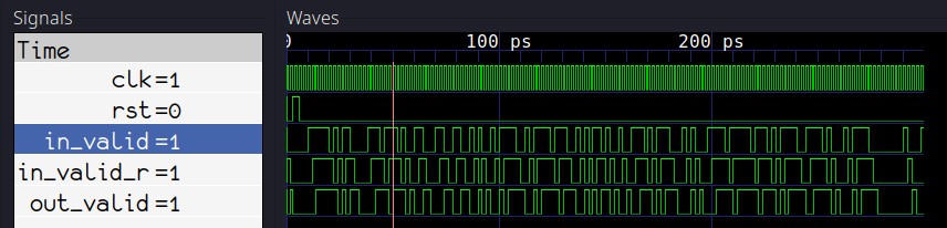 Fig. 6: Updated simulations with random valid
Finished testbench ⌗
Here is the current finished version of our C++ testbench:
#include <stdlib.h>
#include <iostream>
#include <cstdlib>
#include <verilated.h>
#include <verilated_vcd_c.h>
#include "Valu.h"
#include "Valu___024unit.h"

#define MAX_SIM_TIME 300
#define VERIF_START_TIME 7
vluint64_t sim_time = 0;
vluint64_t posedge_cnt = 0;

void dut_reset (Valu *dut, vluint64_t &sim_time){
    dut->rst = 0;
    if(sim_time >= 3 && sim_time < 6){
        dut->rst = 1;
        dut->a_in = 0;
        dut->b_in = 0;
        dut->op_in = 0;
        dut->in_valid = 0;
    }
}

void check_out_valid(Valu *dut, vluint64_t &sim_time){
    static unsigned char in_valid = 0; //in valid from current cycle
    static unsigned char in_valid_d = 0; //delayed in_valid
    static unsigned char out_valid_exp = 0; //expected out_valid value

    if (sim_time >= VERIF_START_TIME) {
        out_valid_exp = in_valid_d;
        in_valid_d = in_valid;
        in_valid = dut->in_valid;
        if (out_valid_exp != dut->out_valid) {
            std::cout << "ERROR: out_valid mismatch, "
                << "exp: " << (int)(out_valid_exp)
                << " recv: " << (int)(dut->out_valid)
                << " simtime: " << sim_time << std::endl;
        }
    }
}

void set_rnd_out_valid(Valu *dut, vluint64_t &sim_time){
    if (sim_time >= VERIF_START_TIME) {
        dut->in_valid = rand() % 2;
    }
}

int main(int argc, char** argv, char** env) {
    srand (time(NULL));
    Verilated::commandArgs(argc, argv);
    Valu *dut = new Valu;

    Verilated::traceEverOn(true);
    VerilatedVcdC *m_trace = new VerilatedVcdC;
    dut->trace(m_trace, 5);
    m_trace->open("waveform.vcd");

    while (sim_time < MAX_SIM_TIME) {
        dut_reset(dut, sim_time);

        dut->clk ^= 1;
        dut->eval();

        if (dut->clk == 1){
            dut->in_valid = 0;
            posedge_cnt++;
            set_rnd_out_valid(dut, sim_time);
            check_out_valid(dut, sim_time);
        }

        m_trace->dump(sim_time);
        sim_time++;
    }

    m_trace->close();
    delete dut;
    exit(EXIT_SUCCESS);
}
You can also get all the finished sources as described here.
Conclusion ⌗
The way C++ testbenches are written is certainly different from how one would design a testbench in Verilog/SystemVerilog, but from the examples given in this guide, you can see how individual functional pieces that would be written in Verilog look similar in C++. Building an intimate understanding of the correct ordering of C++ calls to create clock edges, stimulate/check signals, and dump waveform values is therefore critical if you want to apply your Verilog testbench writing skills to C++.
And although the current version of our testbench is still quite basic, it is already starting to resemble a more advanced verification environment. The testbench now initializes all signals to random values, and contains both random stimulus and continuous assertion-like monitoring of at least one of the outputs.
What’s next? ⌗
In Part 3, we will continue expanding our C++ testbench to verify the addition and subtraction functionality of our ALU.
If you have any questions or observations regarding this guide ⌗
Feel free to add me on my LinkedIn, I’d be happy to connect!
Or send me an email: