Verilator Pt.3: Traditional style verification example

In Part 1 and Part 2, we have discussed the basics of using Verilator and writing C++ testbenches for Verilog/SystemVerilog modules, as well as how to perform essential verification tasks: driving inputs, observing outputs, generating random stimulus and implementing continuous assertion-like checking.
In this guide, we will take a look at writing a simple testbench to verify the addition and subtraction functionality of our ALU.
Getting started ⌗
This guide is a direct continuation from Part 2. You can get the finished sources for the example Verilator project used in this tutorial from Github and explore as you wish:
    git clone https://github.com/n-kremeris/verilator_basics
    git checkout verilator_pt3
Or, follow the guide below as we continue from Part 2.
Making the operation_t typedef available in the C++ testbench ⌗
Before we can start checking that our ALU correctly adds or subtracts two numbers, we must first make our operation typedef available for us in our tb_alu.cpp testbench.
At the top of our ALU code, we have the following:
typedef enum logic [1:0] {
     add     = 2'h1,
     sub     = 2'h2,
     nop     = 2'h0
} operation_t /*verilator public*/;
Notice the /*verilator public*/ comment, after the operation_t name. This tells verilator to convert this typedef to C++, and make it publicly available - this happens during the verilation (HDL to C++ conversion) step.
These types of comments are called directives, or pragmas - they give Verilator additional information on how to process your HDL code. You can find a list of them in the Verilator Language Extensions guide.
If you look at the folder obj_dir, where our conversion artifacts are located, you will find Valu___024unit.h, which contains the verilated version of our typedef enumeration:
    // TYPEDEFS
    // That were declared public
    enum operation_t {
        add = 1U,
        sub = 2U,
        nop = 0U
    };
If we wouldn’t have added the /*verilator public*/ comment, this typedef would not be provided in our header file.
As we have already included this header in our tb_alu.cpp (#include "Valu___024unit.h"), we can now use the definitions inside the enum to drive the op_in input of the ALU.
The enum values can be then be accessed in our testbench as follows:
Valu___024unit::operation_t::add
Valu___024unit::operation_t::sub
NOTE: If the DUT you’re working on has submodules, and you use the public directive inside any of the submodules, you may need to find and include additional header files generated from those specific submodules.
At this point we have everything we need to go ahead and verify our ALU’s addition and subtraction functionality.
Traditional (time based) verification example ⌗
In Part 2, a primitive tesbench design method was demonstrated, which verified that our ALU’s output valid works correctly.
We checked that the pipeline between in_valid and out_valid works correctly by applying 1 to in_valid on the 5th clock cycle, and checking that out_valid is 1 on the 7th clock cycle:
if (posedge_cnt == 5){
    dut->in_valid = 1;       // assert in_valid on 5th cc
}
if (posedge_cnt == 7){
    if (dut->out_valid != 1) // check in_valid on 7th cc
        std::cout << "ERROR!" << std::endl;
}
This example by itself is rather poor (what if out_valid is permanently stuck 1?), but works well to illustrate the point. I personally call this traditional, or time based verification style, because we explicitly apply some specific input values at specific times, and check that the output values match what we expect after some time has elapsed. This style is great for quickly verifying small designs, though might not be the best option when dealing with complex modules.
Time based stimulus ⌗
If you’re following this guide after finishing Part 2, your main loop should now look like this:
while (sim_time < MAX_SIM_TIME) {
    dut_reset(dut, sim_time);

    dut->clk ^= 1;
    dut->eval();

    if (dut->clk == 1){
        dut->in_valid = 0;
        posedge_cnt++;
        set_rnd_out_valid(dut, sim_time);
        check_out_valid(dut, sim_time);
    }
    m_trace->dump(sim_time);
    sim_time++;
}
Let’s do an addition operation on clock cycle 10, and a subtraction operation on cycle 20. To do this, we will remove the random valid send function that’s on Line 10 above, and replace it with a switch statement as follows:
while (sim_time < MAX_SIM_TIME) {
    dut_reset(dut, sim_time);

    dut->clk ^= 1;
    dut->eval();

    if (dut->clk == 1){
        dut->in_valid = 0;
        posedge_cnt++;
        switch (posedge_cnt){
            case 10:
                dut->in_valid = 1;
                dut->a_in = 5;
                dut->b_in = 3;
                dut->op_in = Valu___024unit::operation_t::add;
                break;

             case 20:
                 dut->in_valid = 1;
                 dut->a_in = 5;
                 dut->b_in = 3;
                 dut->op_in = Valu___024unit::operation_t::sub;
                 break;
        }
        check_out_valid(dut, sim_time);
    }

    m_trace->dump(sim_time);
    sim_time++;
}
As you can see, in both cases we set dut->in_valid to 1, set some input operands in dut->a_in and dut->b_in, and then set the dut->op_in to our desired operation: addition on the 10th clock cycle, and subtraction on the 20th. When simulated, we can see how that works in fig. 1:
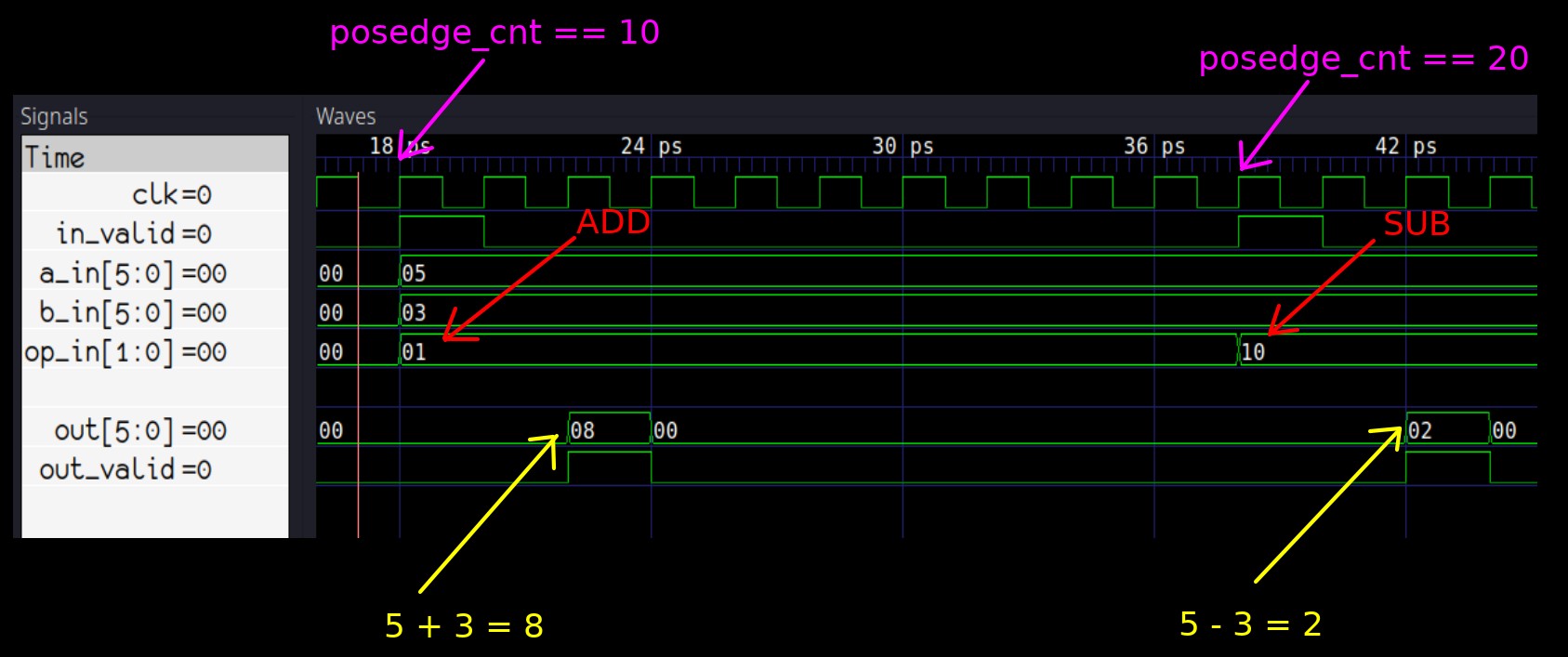 Fig. 1: Addition and Subtraction simulation results
From Fig. 1, we can see that the ALU works correctly, but we should really be doing the checks in the code.
Time based result checking ⌗
We know that the ALU pipeline will always take a fixed number of 2 clock cycles to process our inputs and return a result at the outputs, so we can add checks on the 12th and 22nd clock cycles to verify the results:
switch (posedge_cnt){
    case 10:
        dut->in_valid = 1;
        dut->a_in = 5;
        dut->b_in = 3;
        dut->op_in = Valu___024unit::operation_t::add;
        break;

     case 12:
        if (dut->out != 8)
            std::cout << "Addition failed @ " << sim_time << std::endl;
        break;

     case 20:
         dut->in_valid = 1;
         dut->a_in = 5;
         dut->b_in = 3;
         dut->op_in = Valu___024unit::operation_t::sub;
         break;

     case 22:
        if (dut->out != 2)
            std::cout << "Subtraction failed @ " << sim_time << std::endl;
        break;
}
We don’t need to explicitly verify that the out_valid is correct in cases 12 and 22 - that is still being done by our check_out_valid() function.
If we run the simulation now, we’ll see that it passes without any problems, because the ALU is written correctly. However, if we go into alu.sv and mess with the result vector:
//sub: result = a_in_r + (~b_in_r+1'b1); // original
sub: result = a_in_r + (~b_in_r+6'h3);   // modified
We will see that the simulation fails and tells us where the problem was detected:
### SIMULATING ###
./obj_dir/Valu +verilator+rand+reset+2
Subtraction failed @ 42
Conclusion ⌗
This guide demonstrates a primitive verification code in C++ example that can be used for basic verification tasks. There are many variations on how you can structure this kind of code - you can use switch statements like shown here, individual if statements, or split the code out to separate functions. However, you can probably agree that this kind of verification methodology, while basic and quick to implement, is not really sufficient for more complex designs.
What’s next? ⌗
Now that you have built a good understanding on how to stimulate and check your design with Verilator, Part 4 will demonstrate how to write randomised transactional (UVM style) testbenches in C++.
If you have any questions or observations regarding this guide ⌗
Feel free to add me on my LinkedIn, I’d be happy to connect!
Or send me an email: